
Engineering Blog and Portfolio

Posted: 23 MAY 2024
Week of 24 MAY 2024
This week was spent finalizing a many parts of the golf cart control system, crimping wires and documenting.
Firstly, and this was partially done last week already, I completed a final, in terms of functionality, circuit board. It is still however labeled version 0.3 as it is untested and implements a few new features.
Below I have included the schematic for the circuit board.
While the schematic is decently labeled, it could certainly still use some work, particularly on the second page.
One of the main differences here is the presence of a new DAC. This one communicates over SPI instead of being a parallel interface - thus taking fewer pins -, occupies less space on the PCB, and most importantly: costs about 20 times less to replace.
The old DAC was and old but very high precision model that is no longer in production, so getting something pin compatible would cost around $20 dollars per part, the new one costs just over $1. This saves nearly half of the circuit board's cost!
Below is an image of the new DAC from the schematic:


The new board also comes with some slight improvements on the layout. The PCB is shown below:
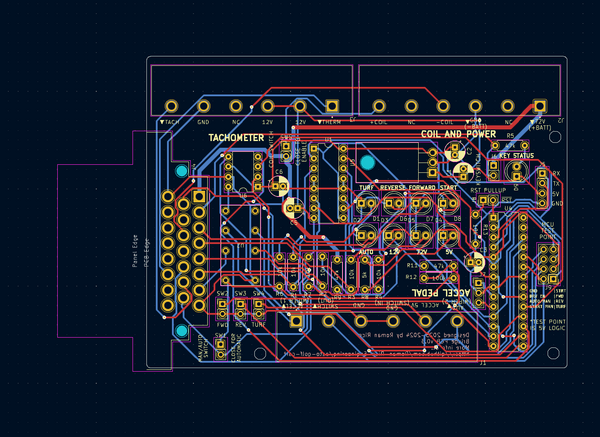
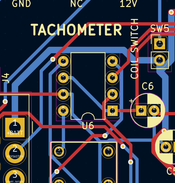
Here you can see the smaller form factor of the new DAC:
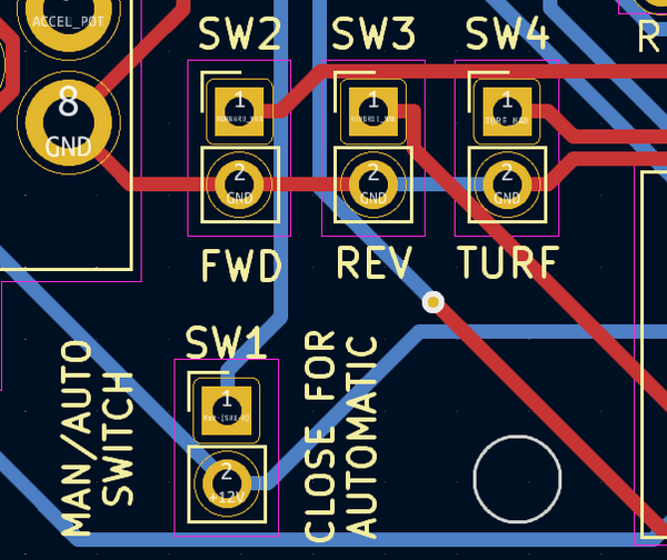
Also this circuit board has some added connectors to simplify the manual control interface:
Of course as with previous circuit boards, everything is labeled in great detail on the silkscreen. This board however also adds some improvements to existing labels:

Arrows pointing inwards, towards center of circuit board, represent inputs.

In parentheses are added labels to clarify some previously ambiguous connections and better match the golf cart's electrical datasheet.
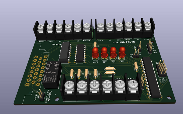
Below is a 3D rendering of the new PCB:

Also the new circuit board features credits and some useful references to additional information:

This week much work went into finalizing the firmware for the v0.2 circuit board. Primarily I made a number of alterations to simplify alterations and implement a text based interface. Of course as with all text based serial interfaces, a great deal of care must be taken in order to ensure that it works reliably, this took up a very large amount of time and will still require better testing, as well as cleaning up a few points that I mention later in the blog post.
Firstly, an important part of this week's progress in the firmware was rooting everything in a config file.
Below shown (config.h):

This config file should be the only thing that needs to be updated between different versions of the circuit board, apart from dedicated drivers for new components.
For example, the v0.3 PCB will require a new implementation for the following header file (dac.h):
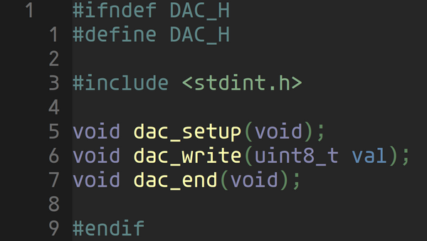
As this code is nicely separated it should now be significantly easier to maintain.
Also, in the code I worked on a very interesting string parsing module, which, in order to work efficiently had to implement many low level mechanics which are present to some extent in many standard c functions but which would not fit nicely into the very restricted context in which the string parsing needs to occur.
The way this works is simply that there is a buffer with a moving head pointer that stores data and then there are a few utility functions which allow for identifying the command after a newline is detected.
Below is the header file:
And the actual implementation:
The interface that this code helps to implement is as follows (inspired by GRBL):
$<COMMAND>=<VALUE>\n for writing
or
$<COMMAND> for reading
For example, to enable the forward mode on the golf cart the command would be:
$FORWARD=1\n
To disable:
$FORWARD=0\n
And to read its current value:
$FORWARD\n
As a response to each write the board will either respond
'ok\n'
or
'err\n'
For read operations:
'<VALUE>\n'
'ok\n'
or
'err\n'
To the right is the
original idea for the
interface, which is now
implemented:
While this code works very well and very reliably, there are other parts to the code which may still require some small modifications. The main one of these places of possible improvement is shown below:
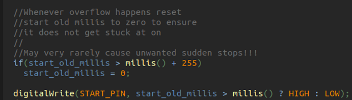
Because the automatic control uses millis() to keep track of how long the start switch has been on and when to turn it off, unsigned long overflow needs to be dealt with in some way to avoid possibly catastrophic system failure, i.e. the golf cart being stuck in an on state. The above code will solve this problem however it is not ideal and I would still like to have some more people look over it (Any feedback is welcome if this is during the weekly blog post reading at robotics).
Finally, this is all of the files for the golf cart firmware:

Apart from improving the documentation the firmware for the v0.2 PCB is now complete!
Overall I am very glad to say that the project is finally in a state where it allows for TRUE backseat driving without the need to be an expert in general relativity, quantum mechanics, string theory, or the dutch language:
Apart from the golf cart, I also made a small contribution to Shubh's pen plotter with finalizing some parts of his circuit board design.
These changes included changing the operation voltage of the microcontroller to 3v3, removing the bidirectional level converter, adding additional traces for communicating between the GRBL control and RPi, and fixing some small inconveniences concerning the UART interface for programming the microcontroller and interfacing with GRBL directly from the RPi.
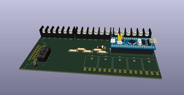
This week the circuit board for that finally got here:


The circuit board is not yet soldered so here is a 3D rendering which includes some of the components (main visible changes are use of atmega328p microcontroller, connectors, and extra motor driver slot):

P.S.
The voltage converter SMD footprint is now also fixed, so it will be easier to solder and not require tape on the bottom of the board to prevent shorts.
Posted: 16 MAY 2024
Week of 16 MAY 2024
This week I started by assembling a new fuse holder and power supply for the golf cart. I ommited to take a picture of the finished product but this is what the wiring looked like beforehand, just as a reference for why it needed to be fixed:

More importantly however this thursday I soldered a new circuit board, below I have images of the three versions I have tested so far, on the bottom is the latest.
This circuit, so far seems to work perfectly!
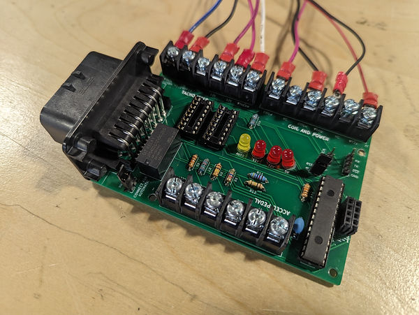
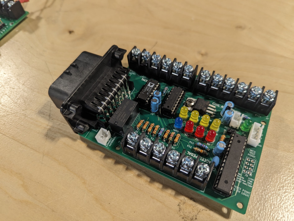
Latest circuit board:
Posted: 8 FEB 2024
Week of 26 APR 2024
The image on the bottom is the new revised circuit board design. As can be seen by the picture, the design if far more compact and wherever possible replaces larger components with more distinct functions with more application specific integrated solutions.
What is also most important is that this revision of the circuit board no longer uses PMOS transistors. The fact that the controller must be driven by a voltage of more than +12V, and sometimes more than +72V, (a positive voltage) means that NMOS would not be effective in solving this problem and that using PMOS, we will see many difficulties in driving the gate. As such this was replaced by an IC.
This week I assembled a new circuit board that fixes problems with the old circuit board. Because this circuit board fixes the problems with the old one, it works better. This circuitboard is also smaller, so it takes up much less space as compared to the old design which took up far more space than what was required to accomplish its purpose.
Posted: 8 FEB 2024
Week of 8 MAR 2024
In order to fix this problem it is important to understand what it is caused by. This problem lies in the fact that the mosfets which I am using are PMOS, meaning that their gate needs to take an input as a voltage differential from the switching power, and not ground.
This is something which makes designing circuits using PMOS complicated as ground is normally used as a reference but here it has to be the inverse.
The important detail which I ommited when designing the circuit was that one of the mosfets needed to swtich a 72V input, however I ommited to correctly set up the schematic in order to keep the gate source voltage differential to less than the breakdown(max) value.
As such for one of the mosfets I will have to use some external circuitry to correctly control the drive. For the final circuit in particular I intend to use dedicated mosfet drives for all of them to ensure that such problems do not happen.
In the future I intend to use a dedicated mosfet driver circuit to ensure that the gate source voltage limits are upheld as well as making sure that the circuit is simple and efficient.
As I started to work on assembling it, luckily before soldering the mosfet driver circuitry I found I very noticible flaw with the mosfet driver circuit.
This is approximately what the circuit should have looked like originally:


Posted: 29 FEB 2024
Week of 29 FEB 2024
This problem lies in the fact that the mosfets which I am using are PMOS, meaning that their gate needs to take an input as a voltage differential from the switching power, and not ground.
This is something which makes designing circuits using PMOS complicated as ground is normally used as a reference but here it has to be the inverse.
The important detail which I ommited when designing the circuit was that one of the mosfets needed to swtich a 72V input, however I ommited to correctly set up the schematic in order to keep the gate source voltage differential to less than the breakdown(max) value.
As such for one of the mosfets I will have to use some external circuitry to correctly control the drive. For the final circuit in particular I intend to use dedicated mosfet drives for all of them to ensure that such problems do not happen.
Originally this was not caught because I did most of the testing at lowever voltages that did not interfere with this, now however, I feel that I have much better learned how to work with PMOS and believe that this will be of great use to me in the future.
* In the image below please reffer to the lack of any circuit to deal with voltage division on the mosfet's input.
This week the circuit board for the motor control arrived and I began work on getting it to function properly.
However as I started to work on assembling it, luckily before soldering the mosfet driver circuitry I found I very noticible flaw with the mosfet driver circuit.

This week I continued work on debugging the motor controller. What seems to remain for testing is attempting to narrow what part of the control circuit is not working.
For this I am attempting to measure the voltages of the output terminals on the motor controller.It is important to make sure that the outputs are set to the correct voltage and are in fact being driven.
The motor controller has been non functional in a very strange way. It seems to work completely fine except for the fact that it does not produce any motor driver output or RS232 communication.
As these are the only two useful things that this motor controller does when it works correctly, its pretty safe to say that it is not working correctly.
So far I have tested the power supply in the controller and determined that it is not if fact that which causing the issue.
Currently I am investigating a few other possible causes of this and with help from Bob I am sure we will be able to find the reason why it does not work.


Posted: 16 FEB 2024
Week of 16 FEB 2024
This week I also completed the design for a simplified PCB for controlling this motor driver. It does not have all of the complex error correction functionality or specific connectors which are present on the full circuit board however it should be enough to test some of the basic control and switching capabilities between automatic and manual control. Shown below is the basic usage diagram provided in the datasheet which I have been using.

This week I continued work on debugging the motor controller. What seems to remain for testing is attempting to narrow what part of the control circuit is not working.
For this I am attempting to measure the voltages of the output terminals on the motor controller.It is important to make sure that the outputs are set to the correct voltage and are in fact being driven.
The motor controller has been non functional in a very strange way. It seems to work completely fine except for the fact that it does not produce any motor driver output or RS232 communication.
As these are the only two useful things that this motor controller does when it works correctly, its pretty safe to say that it is not working correctly.
So far I have tested the power supply in the controller and determined that it is not if fact that which causing the issue.
Currently I am investigating a few other possible causes of this and with help from Bob I am sure we will be able to find the reason why it does not work.
Posted: 16 FEB 2024
Week of 16 FEB 2024
This week I also completed the design for a simplified PCB for controlling this motor driver. It does not have all of the complex error correction functionality or specific connectors which are present on the full circuit board however it should be enough to test some of the basic control and switching capabilities between automatic and manual control. Shown below is the basic usage diagram provided in the datasheet which I have been using.
This week, following advice given to me by Mr. Christy, I got some help with debugging the broken motor controller from Bob.
The motor controller has been non functional in a very strange way. It seems to work completely fine except for the fact that it does not produce any motor driver output or RS232 communication.
As these are the only two useful things that this motor controller does when it works correctly, its pretty safe to say that it is not working correctly.
So far I have tested the power supply in the controller and determined that it is not if fact that which causing the issue.
Currently I am investigating a few other possible causes of this and with help from Bob I am sure we will be able to find the reason why it does not work.

Posted: 01 FEB 2024
Week of 08 FEB 2024
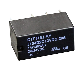
Another thing which I worked on this week is finding, once again, the correct relay. This was caused by my discovery that the relay I had previously found, while rated at over 200 volts AC, was only rated for 30 volts DC, far less than what I would require to switch the golf cart's power supply reliably(Just another example of how useful rereading a datasheet before building something or ordering a part can be).
In looking at different relays however, I noticed that generally, power relays, have very low DC voltage ratings while signal relay have low current ratings. As well as this, solid state relays seem to handle both rather well, but in my mind there is always some added trust to an actual mechanical switch working to save my curcuit from imminent self destruction.
Below I have images of some of these relays, on the right is a 10A power relay, only rated at 30VDC (although 277VAC). In the middle is the tiny solid state relay, rated for up to 100 volts and 3.5 amps. And finally on the left is a signal relay, rated for up to 100VDC but only 2A of current.
This week, after giving charging the golf cart myself a final attempt. I brought the batteries up to automotive in order for them to be charged by the dedicated car battery chargers.
At the same time I started figuring out how the battery charger on the ford think itself works.
In this process I actually discovered a few things which are very important which I very well may have never notives if the charger did not stop working.
Firstly, and most importantly is that the battery charger expects a temperature input from the batteries, which, while the sensor was in place, the batteries we are currently using being too small for the dimensions of the golf cart caused the sensor to not make proper contact.
This while not the only possible reason for it not working could certainly cause problems later in our using the golf cart for future autonomy design.


There is however a fair amount more for me to find out about this charger which I will report about in future blog posts


Posted: 01 FEB 2024
Week of 01 FEB 2024
Another thing which I worked on this week is finding, once again, the correct relay. This was caused by my discovery that the relay I had previously found, while rated at over 200 volts AC, was only rated for 30 volts DC, far less than what I would require to switch the golf cart's power supply reliably(Just another example of how useful rereading a datasheet before building something or ordering a part can be).
In looking at different relays however, I noticed that generally, power relays, have very low DC voltage ratings while signal relay have low current ratings. As well as this, solid state relays seem to handle both rather well, but in my mind there is always some added trust to an actual mechanical switch working to save my curcuit from imminent self destruction.
Below I have images of some of these relays, on the right is a 10A power relay, only rated at 30VDC (although 277VAC). In the middle is the tiny solid state relay, rated for up to 100 volts and 3.5 amps. And finally on the left is a signal relay, rated for up to 100VDC but only 2A of current.
This week I worked on a few things one of which was charging the golf cart. The voltage of the total battery pack has so far fallen to about 74.3-74.5 volts, while this range is still fine for the batteries, it is definitely slowly becoming discharged. However, in my attempts at charging the golf cart so far this week I was unsuccessful. While the charging circuit was activated, it seemed that that was something preventing the charge from reaching the battery pack of the golf cart, such as, possibly, one of the parts I removed in my work on the motor control system(which I have not yet replaced), being necessary for the charging to work correctly. As such I will now need to consult the datasheets for the golf carts wiring as well as for the charging module to find the problem.
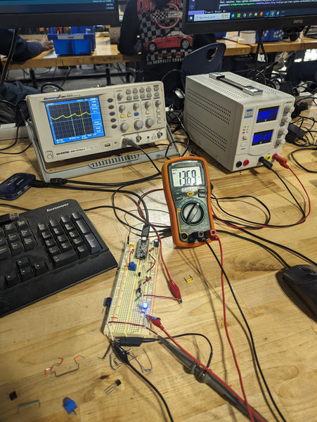
As well as this, this week I worked on making some calculations for the circuit board to make sure that it will work reliably before ordering. I both did some testing on a breadboard and, where I spent the most time, spent time consulting datasheets, comparing the capabilities of components, and calculating current draws. In this process the online trace width calculator, (shown below), was greatly useful.

Interesting Observations
Beyond simply the work on my project, I briefly assisted Shubh Patel with debugging a circuit board for his pen plotter project. In this proccess I noticed a very interesting detail about the metro mini microcontroller, one which is often used in the Robotics and Engineering shop.
Posted: 26JAN 2024
Week of 26 JAN 2024
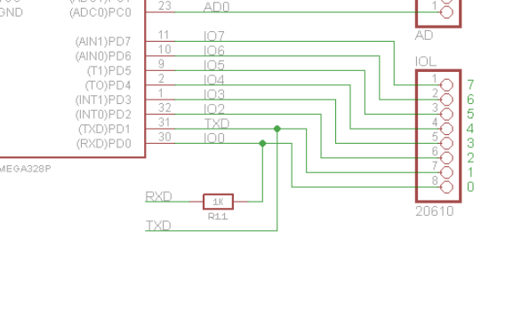
This interesting feature of the metro mini is related to the USB-UART bridge located on the PCB. This is a component which is needed as the actual atmega328p chip which is used on the metro mini is unable to communicate over USB, or rather does not provide a USB interface.
This chip converts between USB, which is connected to the external USB port and the two pins on the atmega328p which are mapped to the UART state machine inside of the actual microcontroller chip. These pins however, are also accessible as simply GPIO outputs on the metro mini, or for use in actual UART to UART communication as designated by the firmware designer.
This however poses a risk that both the UART-USB converter chip and the GPIO/UART outputs on the metro mini, may be attempting to drive the two lines to simultaniously ground and power, resulting in a short circuit.
As the metro mini is a board largely aimed at people just beginning to learn about embedded software and firmware development. Such a vulnerability could cause very substantial problems.
To solve this, the designers at adafruit made it so that the UART-USB convertor chip is only connected to the metro mini through a 1k resistor. This means that the short circuit scenario described earlier can no longer occur, however it leads to the possibility of other unusual behavior arising.
While this is a generally good feature, it means that using the metro mini with other boards, such as the adafruit bidirectional logic level converter, can cause problems. In this case, the bidirectional logic level converter uses a combination of mosfets to drive the lines low and pullup resistors to drive the line to a high state. As you may have already guessed, these pullup resistors just so happen to also be about 1k in strength, This means that as much as the USB-UART converter tries, it will never be able to drive the line to below 2.5V and as such, the metro mini will never be able to read a low state on the line or, thus, see transmitted data.
This week I worked with Shubh to help him set up his docker container. As I have worked with docker a fair amount in the past I helped with the setup.
Afterwords I got back to my circuit board and worked on it and reached a problem. This problem was based on my not sufficiently understanding how transistors works.
After looking at what I already had working I decided that there was still one more thing to add to the error detection circuit which was the emergency shutdown, for this I simply made the error detection controller connect to a few relays which control the main power, this is not shown in the images as I did this later.
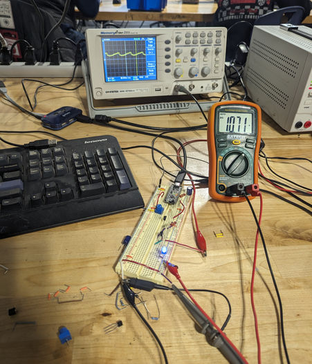
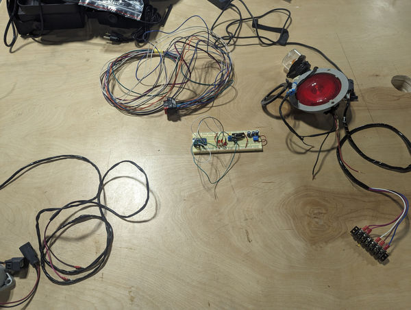
Finally, here is an image showing most of the parts which I got working lying on the table, the last thing needed to get them to work is the circuit board which I am working on doing the PCB layout for currently.
Posted: 19 JAN 2024
Week of 19 JAN 2024
This week, I got the last few parts of the circuit working on the breadboard prototype which together with the designs which I already tested as a circuit board allowed for me to begin work on the layout for the final circuit board. The error detection circuit shown above was the main thing which I needed to add.

After looking at what I already had working I decided that there was still one more thing to add to the error detection circuit which was the emergency shutdown, for this I simply made the error detection controller connect to a few relays which control the main power, this is not shown in the images as I did this later.
Finally, here is an image showing most of the parts which I got working lying on the table, the last thing needed to get them to work is the circuit board which I am working on doing the PCB layout for currently.
Posted: 11 JAN 2024

Week of 11 JAN 2024

Week of 22 DEC 2023
This week I worked on both the software and the hardware of the golf cart controller, in particularly I attempted to simplify some of the wiring by using more communication protocols in place of what was previously parallel communication of data.
Posted: 22 DEC 2023
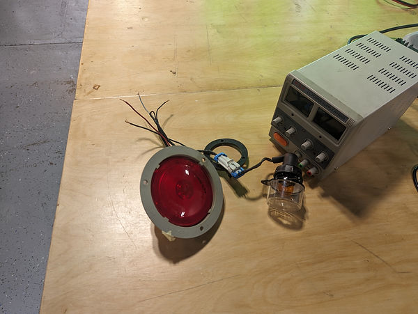
Last week I did not quite have enough time to talk about the way the golf cart lights work.
The three wires on the red light are as follows
WHITE - GROUND
RED - FULL ON +
BLACK - PARTIAL ON +
The two wires on the other light are simply
BLACK - GROUND
WHITE/BLUE - POWER
This is an image of the way the lights are connected.
This week while I was worked at simplifying wiring I ran into issues with wires being of different voltages, being able to supply different currents or even that signals would have to only exist in software, over some communication protocol.
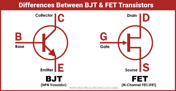
In order to solve this issue I had to work with transistors and I ended up learning a fair amount about the differences between BJTs and MOSFETs, something that now I understand is one of the most important parts of electrical engineering. The most important thing I learned is how MOSFETs are activated by a voltage differential, activating a sort of capacitor which controlls switching, while the BJT is activated by current.

Week of 15 DEC 2023
This week I worked on checking the circuits which I have already built, documenting used components, and learning more about how to interface with different microcontrollers, including AVRs, STM32s, ESP32s, etc.
(particulary from CLI). This has allowed me to far better understand how microcontroller bootloaders work, as well as giving me a good opportunity to use Zephyr RTOS.
Posted: 15 DEC 2023
Using cli tools such as stm-* and openocd, as well as directly using HALs and cross compilers, allowed for me to better understand the process as well as finally explaining to me how such embedded programs could be tested automatically. This particularly seems to be a very useful workflow to go together with git.
This was very useful, however I also worked on documenting some connectors, this was not a very interesting process, however it still took some time and was very useful, or will be very useful in the future.
Finally I also worked on figuring out how the rear lights worked on the golf cart.
This was quite a confusing setup, as there were 4 wires connected in a very strange way. However I was able to find what they do after some research.
The three wires on the red light are as follows
WHITE - GROUND
RED - FULL ON +
BLACK - PARTIAL ON +
The two wires on the other light are simply
BLACK - GROUND
WHITE/BLUE - POWER
This is an image of the way the lights are connected.


Shown above:
When prototyping does not go right

A possible solution to an unnecessary problem is shown above.
During this week I made a motor be able to control a circle. This great feat was accomplished using buttons. Sadly versions 1, 2, 3, 4, and 5 of Circle
(Made by Joao) broke during experimentation. Later, version 1 of Circle made by me also broke. This is promising for the future as it means the motor is stronger than a flimsy piece of cardboard.
Posted: Friday, 04 nov 2022

During this week I ventured into the realms of binary information storage, signals, pulses, and serial communication as I started developing my own communication protocol, the RWCP project. More details on the progress I made can be found on the project's initial development blog, here.
Posted: Thursday, 27 oct 2022

There was very little progress made this week as shown in the illustration.
This week I accomplished:
-
Drawing a cool progress chart
-
Finding a reason to not use every single communication protocol that already exists
Posted: Thursday, 20 oct 2022

Image of raspberry pi's list of I2C connections
During this week I accomplished:
-
Learning Basic Bash Scripting
-
Using python to connect to Arduino via I2C
This will later be used to help centralize the golf cart's control and override systems.
Posted: Thursday, 13 oct 2022

During this week I finished organizing the project's organization as well as being working on the control scheme for the golf cart.
Posted: Friday, 06 oct 2022

This week I finished the steering portion of the golf cart 3D model as well as mapping out the golf carts future control scheme and doing some research into its future remote control features
The golf cart project should now be able to start progressing at full speed!
Posted: Friday, 30 Sept 2022

During this week I created a 3D model for the frame of the golf cart that is being used for the Self Driving Golf Cart Project
The 3D model currently has all of the main structural elements needed for the project.
Soon the steering, braking, and other moving components will be added
Posted: Thursday, 22 sept 2022

This is the first full week of robotics & engineering for 2022-2023
This week I started preparations for this year's Golf Cart Project
This includes:
-
Reassembling Seats
-
Labeling Wires
-
Cleaning the Golf Cart
Posted: Friday, 16 sept 2022